Output Solids
The "Output Solids" frame contains a table with all output solids. On the left side, it is possible to select the objects to display - output solids, interfaces, terrain, GWT.
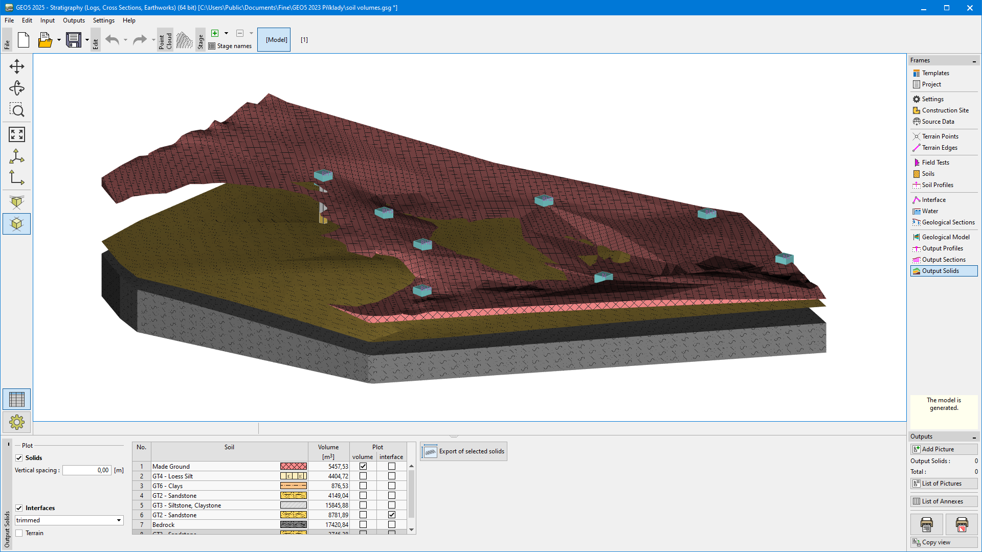 Frame "Output Solids"
In the case of output solids and interfaces, it is possible to display only some items using the checkboxes in the table.
The selected solids can be exported to CAD format as "3D Solid" type by clicking "Export of selected solids". If the solid cannot be exported directly as "3D Solid" (e.g. it contains holes), the program will export it as an entity of type "Mesh". Often this solid can then be converted to 3D Solid in various CAD programs. The success of exporting 3D solid types often depends on the mesh refinement - it is usually easiest to export solids without refinement.
It is possible to define vertical spacing between output solids for better clarity of the layout of the layers. When defining the vertical spacing, only the output solids can be displayed.
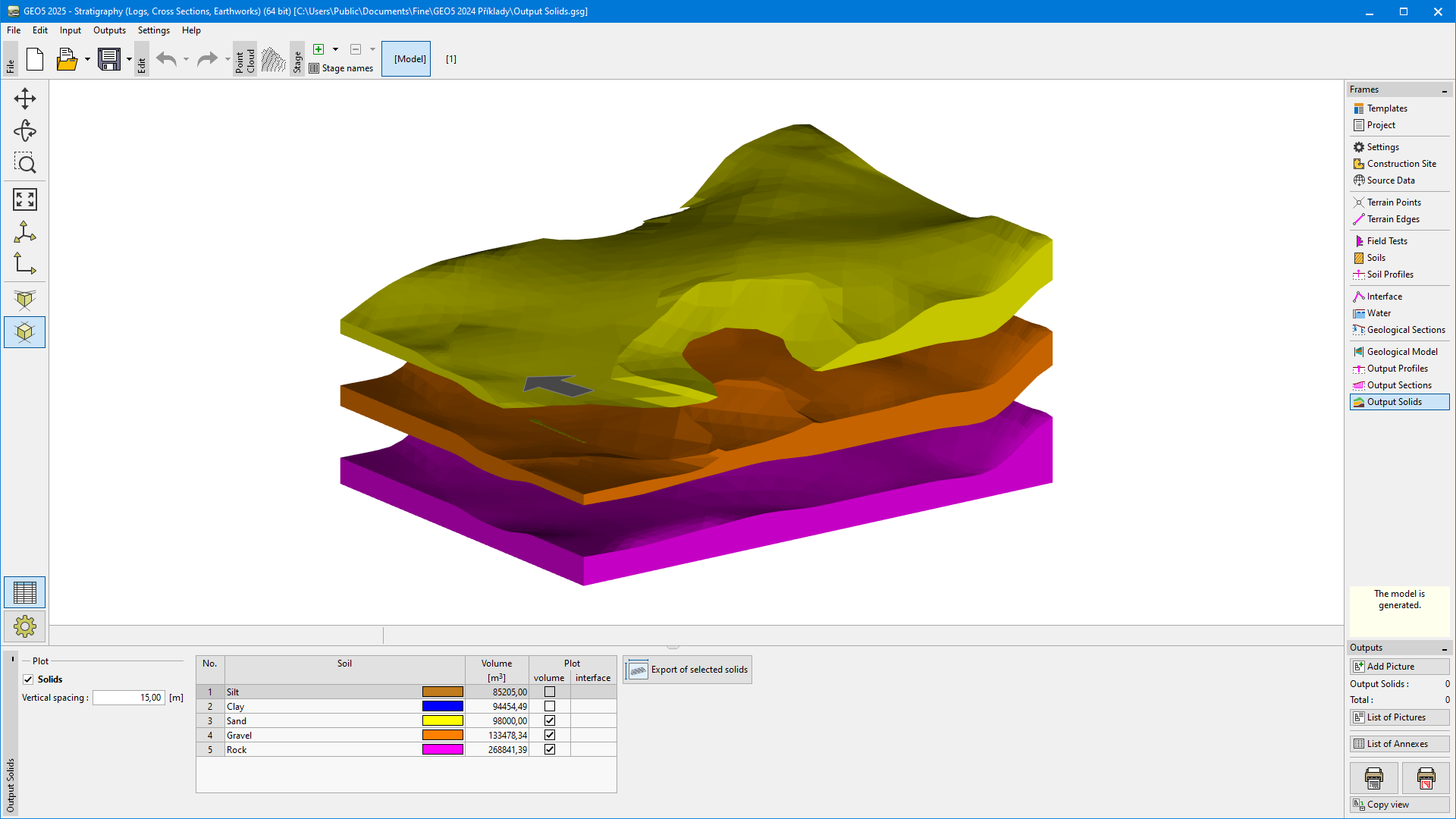 Output solids with vertical spacing
Interfaces can be rendered as "trimmed" (as considered in the model) or "not trimmed" (without cutting by terrain or other interfaces). The display of uncut interfaces is used to get a better idea of the layout of the layers. The interfaces are cut depending on the generation order of each layer.
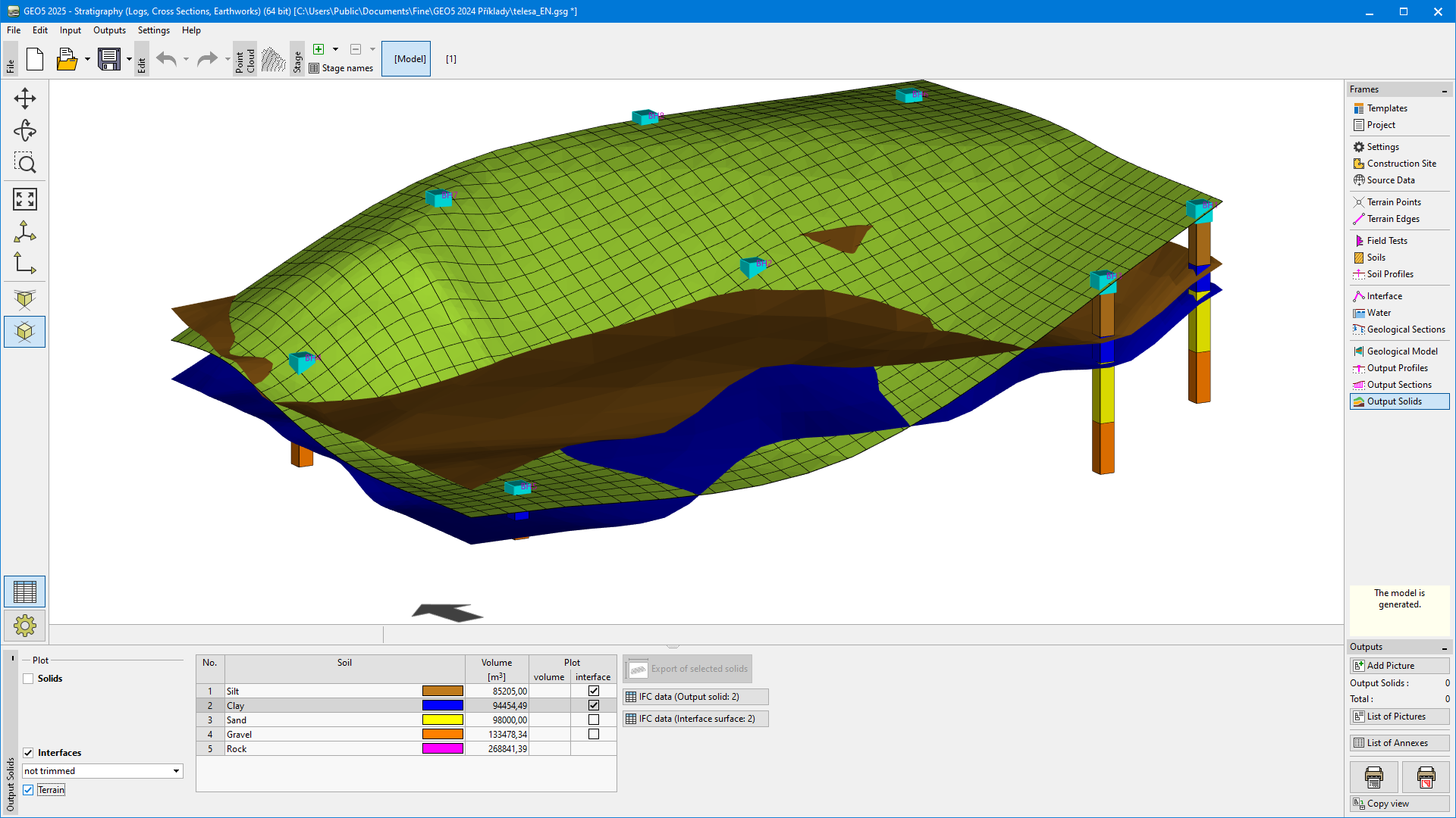 Displaying "not trimmed" interfaces
Visualization of drawing on the desktop can be modified in the "Drawing Settings" frame and with the help of buttons on toolbar "Visualization".
The "Undo" button is an important program tool. It allows us to return back to the original state before any modification.