Verification of Spread Footing for Punching Shear
It is loaded by the prescribed moments MSdx, MSdy and by the shear force FSd provided by:
![]()
where: | A | - | area of footing |
V | - | assigned vertical force developed in column | |
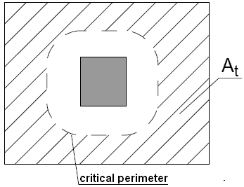
At | - | hatched area in fig. |
 Dimensioning of shear reinforcement area At
The program constructs control sections at distances "a" from 0,5d to 2d in case of footing without shear reinforcement. In case of reinforced footing, the distances are from 0,5d to 4d, where d is the effective depth of footing. The shear reinforcement is considered in control sections, which are in the distance of less than 2d from the column. The control sections are considered in intervals of 0,25d.
The load stress τSd in each control section is found using 19.5.2,
![]()
![]()
K is obtained from table 19.2
the punching shear resistance of footing without shear reinforcement τRd1 follows from 19.5.3.2

![]()
and if necessary the punching shear resistance of reinforced footing τRd3 is given by 19.4.2, 15.5.4.

Furthermore, the compression chord resistance at the column perimeter τRd2 is calculated according to 19.5.3.1. τRd2 depends on column dimensions and the footing thickness.
![]()
![]()
For τSd < τRd1 no shear reinforcement is needed.
For τSd > τRd1 and τSd < τRd2 the shear reinforcement must be introduced.
For τSd > τRd2 the shear reinforcement cannot be designed. It is therefore necessary to increase the cross-section height.
The control section with the ratio of load and resistance with the highest utilization is considered as critical and marked in the program.